C8 Ronchigrams
Inbox
| x |
|  Mon, Jul 1, 8:51 PM (8 days ago) Mon, Jul 1, 8:51 PM (8 days ago) |
| |||


Inbox
| x |
| Mon, Jul 1, 8:51 PM (8 days ago) |
| |||
| Thu, May 2, 1:45 PM (7 days ago) |
| |||


We will get together this Tuesday, July 10 for a workshop. We meet in the Broder Building from 7:30-9 pm. Come join in if you get the chance. Jacques, may we please get the east gate open? Thanks.

I’m not sure where we are with projects, so let’s check in and assess where we are.

I have a new addition to the Dobsonian design- altitude bearings. Now, these are the genius design of Tom Whittemore. Here’s a look:
These altitude bearings slip over the Sonotube ( telescope tube of a Newtonian scope). What is brilliant is they tighten to the sides of the scope when you tighten the knobs you see in the image above. I truly believe in my heart this design could replace all the modern designs we see in magazines and articles.

We need a few tweaks to get there though. Come and speak to these issues.
1). Tube must be smooth
2). The tolerances have to be trued.
3). There is a “ rocking motion” when the bearing assembly is in place. Strategic placement of pads or Teflon pads may take up the “ raw fit” of this assembly.

Also, we may get a little figuring done to get ever closer to finishing an 8” mirror.

See you there.
Tim
——————————
July 10th was my father’s birthday. He was a ship captain most of his life. He used to tell me he had been at sea since Christ was a deckhand.

Without going too far, I just  want to tell you of one incident. ( I had the extreme pleasure of going to to sea with him for a couple of years).

We were in the middle of the Atlantic Ocean. I was a young man just out of City College. I had just finished introduction courses in Physics. My dad came out to the boat deck and asked me if I could tell him how fast we were moving through the water. He gave me a couple of factors and I plugged these into newly studied motion laws.

I gave him my results and he shook his head and said, “ No Timmy. Wrong. You are missing another factor.” I asked him what and he simply said we are on a great circle.

He was using a sextant. That’s all he used to navigate the globe. It was just before GPS became the standard. And yes, he always got us there and almost to the minute. Try to imagine that. It wasn’t too long before that the long sought after “ Longitude” was used at sea.

It may not sound like much but, I got to witness it “live” right in front of my eyes.....
 |
| TimC looking for scratches...found one! Time for a new lap! |
| Tim C 8:17 AM (2 hours ago) to Jerry, Mike, Richard, Tim, me, Tom: Of course I am very sensitive to this. Let's check Tuesday. I am so sorry to hear of these scratches. I am very confused by all of these scratches. It seems to me we have (as a group) never had so many show up in finishing stages. Coincidence? I am not sure. It only takes one grain of grit to do the damage. The question is, " where is the likely source of this contamination?" How does one try to isolate the source? As I have told many of you, in the dental lab, when we have a problem ( not necessarily this kind of problem, but similar) we try to list all the components in the production to the point of the problem, then one at a time change a component till the problem ceases. With the problem at hand, if it cannot be fixed, the problem occurred late in the polishing/ figuring stage. To me, it calls for looking at : A. The environment the problem occurred B. The cerium oxide and container it is in C. The surface you are working on D. The pitch / pitch lap E. Cleaning and storage materials and containers Are there more I have not listed? If it were me, and boy it has been, I think I would group the pitch and cerium into one group. Otherwise changing just one perpetuates the problem mercilessly, while replacing both and fixing the problem still isolates the cause greatly. I do have a question here though. That is, is it really necessary to change these out now? Can Mike go back to 500 then come forward with the same materials, especially the cerium, as it did no damage for a long time? Is the pitch now contaminated or is it just a matter of cleaning the lap carefully? If it is likely that this was a random piece of grit that has now been expelled from the working environment, it is just a matter of being careful with work surfaces and all materials. Again Mike, I am so sorry to hear this and I'm obviously sympathetic. As you know, I am going to go back a sixth time to regrind the donated mirror. I'm going to complete another 8" I have simultaneously. I want to know more of if one piece of Pyrex can be different from another. I still want to know if the cause that persists with this one mirror can come from the blank and not all the other standard components. I did change out all of the others and the scratches persisted. If my methods hold up it seems the problem point to the Pyrex. As Jerry suggests this may be highly unlikely. So that leaves me. Because I work in a very abrasive environment everyday, I may be the source. I may be bringing in contaminants under my fingernails, on my clothes ( which I change before each workshop) or hair. One last component is possible. Randy, from Astrosystems told me he had to put a plastic sheeting above the work area he was in. The acoustic ceiling tiles were a source of contamination for them. As many in the workshop have commented in the past, "it's too bad we do not have a dedicated place we can keep our projects and even a dedicated clean room to polish." T | ||||
MikeIn the ;meantime I need to get serious with a more permanent way of holding the optics. My setup is a handful to keep pointed when the angles are too high and too low. That's because the board used for elevation needs to be adjustable.Thanks for getting back guys.I'll be making the Ronchi eyepiece and masks but won't be able to use them until I get back to Santa Barbara as the cloud cover is solid and might not be gone until a day or so. I might go far as to make another offset circle with a 3.5 inch circle.On Sat, Mar 14, 2015 at 11:22 AM, Richard B wrote:Hi Mike--
Have you ever done a star test on a "perfect" mirror? If you haven't, an easy way to do so is to make a circular off-axis stop about 2 inches diameter for your 10 inch. Use a magnification 1/5 as great, and run a star test. The errors over the small aperture will be small compared to the full miror, and you'll see what a "perfect" image looks like.
The effect you describe -- hard edge one side of focus with soft edge the other side -- is very common. However, the description is qualitative, and that makes it hard to know whether you can ignore what may be a 1/20-wave error or be worried about a 1/2-wave error. I used to take a Ronchi eyepiece (an eyepiece housing with a 100-line Ronchi inside) to star parties, and I looked a lot of mirrors. In general, it's best best to slip in the Ronchi, do your test, and not say anything to the guy who owns the telescope!
I suggest you make a ring-shaped stop with a diameter of 9 inches. Make sure the edge is nice and clean, such as an Xacto-blade cut edge in file-folder cardboard. Just for fun, you could make a mask that cover only 180 degrees of the mirror's rim. If you have a turned-down edge, it probably won't be as much as 1/2 wide, so you see what the star test shows with a non-turned edge.
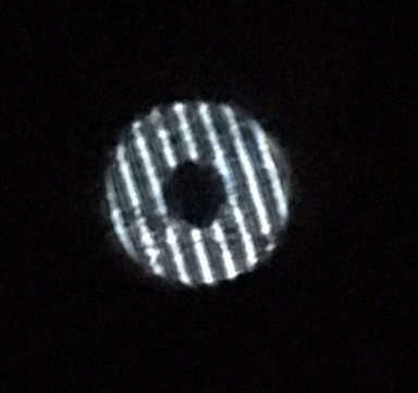
Another useful diagnostic is to place a Ronchi screen at the focus, and view the mirror surface in the light of a star. With four or five bands, they should be perfectly straight. If the bands bow in or out, the mirror is over- or under-corrected.
The purpose of testing on stars is that "you get what you see." There is no math to interpret or figures to misinterpret. The fact that you see errors in the formation of your star images says your mirror will always perform that well and no better. The Ronchi test on a star is essentially a (not very sensitive) null test; straight bands mean good. You can also use a knife edge at focus, but you also see all the air currents.
Testing at center of curvature is good because you do it indoors under controlled conditions, but you're measuring the first derivative of the figure, not the figure itself.
--Richard
On 3/14/2015 8:57 AM, Tim Cwrote:
Hi Mike,
Tom or Jerry are the experts here, but, I want to give you my take- what I would generally interpret first. Then, you can check with Tom, Jerry and Richard for more advice and most likely a clearer explanation.
Before I get there though I would like to say I use a program written by Reifke to interpret my Foucault results. I do not know what algorithm he uses in his program but I like the way it shows results. The pin stick I gave you does not use the same settings for pin placements. You will have to manually measure and change these within the program. The output of this program gives you a picture of the wavefront and where to make changes. It looks like this:
The lower horizontal line is a perfect mirror. The output is the line traced from left to right representing the mirror surface. The vertical lines represent the zones. You can visually see where the correction is needed. Both Tom and Jerry ( actually several others as well) tell me you really can't trust this because the algorithm is unknown.
In Richard's book on page 212, you see the pattern in general you describe showing an over correction. To me, that means the curve is too deep. Where I get all fouled up is visualizing if this means you have too long or too short a radius of curvature. I always seem to get it backward. But, I think it means the radiuses are shorter in an overcorrected mirror. For me, I just visually see a deeper curve or dish if you will. It means we need to flatten the curve.
What I would do, depending on where the errors are on the wavefront is to use TOT and a spherizing stroke in general.
The hard part here is you sent some images that do not represent this exact picture. I am going to search some pictures in Suiter's book a bit and see if I can't find something a little more definitive . In the meantime, yes some Ronchi pictures might really help here. Try for 4-6 lines inside or out. The other thing is, you can wait and we'll all look at this next Tuesday.T
PS- just for fun see if the pin stick placement measurements on my pin stick are the " effective radius" you see in the picture. I believe these are the measurements you would need to manually use in Reifke's program. ( if you choose to check it out)
Sent from my iPad
On Mar 13, 2015, at 9:56 PM, Mike C wrote:
MikeHi Tim:I did center over center last night as per Tom, followed by large w's to blend and got similar results. I'm not sure why things are looking exactly the same in star testing. I see a bright outer ring out of focus and then a diffused circle with bright spot inside focus. That either means that I've got over correction or turned edge. I;ve got to figure out again how to get some decent Ronchi grams to show. Again what does over correction mean with respect to the curve and what part of the curve needs working on?


114%2B.jpg)